 >Support>Technical library>Explanation of current transformer wiring diagram
Explanation of current transformer wiring diagram01-11, 2024
Explanation of current transformer wiring diagram: 4 methods
Current transformers are widely used in measurement and relay protection in factory power supply systems. There are various ways to connect current transformers, which are applied to relay protection in different power supply systems. The wiring method of a current transformer refers to the connection method between the current transformer and the current relay. There are four wiring methods for current transformers in three-phase circuits.
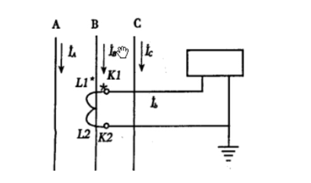
1.One phase wiring methodThe one phase wiring method is shown in the figure, and the current passed through the current coil reflects the corresponding primary circuit
The phase current of the phase is usually used in three-phase circuits with load balancing, such as low-voltage power lines, for measuring current or connecting load protection devices.
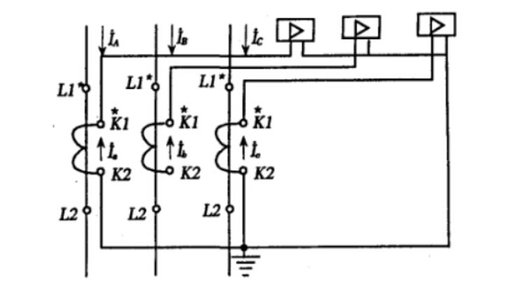
2.Three phase complete star connection
The three-phase complete star connection method is shown in the figure, which works for various faults. When the fault current is the same, it is equally sensitive to all faults, reliable for the same short circuit action, and has at least two relay actions. Therefore, it is mainly used in high-voltage and high current grounding systems, as well as differential protection, phase to phase short circuit protection, and single-phase grounding short circuit protection for large transformers and motors, and in three-phase four wire systems with generally unbalanced loads. It is also used in three-phase three wire systems with potentially unbalanced loads as three-phase current Electricity measurement.
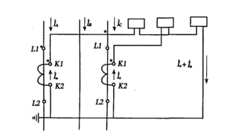
3.Two phase incomplete star connection
The two-phase incomplete star connection is shown in the figure. During normal operation and three-phase short circuit, the current passing through the neutral line is I0=Ia+Ic=- Ib, reflecting the phase current of the phase without the current transformer connected. If two transformers are connected to phases A and C, and there is a short circuit in phase AC, both relays will activate; When there is a short circuit in phase AB or BC, only one relay operates. In a directly grounded neutral system, when a grounding fault occurs in phase B, the protection device does not operate.
So this type of wiring cannot protect all single-phase ground faults and certain two-phase short circuits, but it just meets the requirement of allowing one phase to continue running for a period of time when the neutral point is not directly grounded in the system. Therefore, this type of wiring is widely used in ungrounded neutral systems.
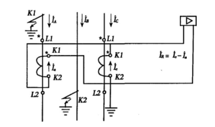
4.Two phase current difference wiring:
The two-phase current difference wiring is shown in the figure. The characteristic of this wiring method is that the current flowing through the current relay is the phase difference IR=Ia-Ib between the secondary currents of two current transformers. Therefore, for different forms of faults, the current flowing through the relay is different. During normal operation and three-phase short circuit, the current flowing through the current relay is three times the current of the secondary winding of the current transformer.
When the A and C phases with current transformers are short circuited, the current flowing through the current relay is twice that of the secondary winding of the current transformer.
When a phase (A and C phases) with a current transformer is short circuited to phase B without a current transformer, the current flowing through the current relay is equal to the current in the secondary winding of the current transformer.
When a single-phase ground short circuit occurs in a phase without a current transformer, the relay cannot reflect its fault current and therefore does not act. Due to the simplicity and affordability of the two phase difference connection method, it can meet the requirements of reliable and sensitive operation in ungrounded neutral systems. Therefore, it is suitable for phase protection of transformers, motors, and lines in ungrounded neutral systems.