 >Support>Technical library>Principle of AC current clamp
Principle of AC current clamp12-19, 2023
Principle:
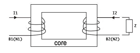
AC current clamp can be regarded as a derivative application of current transformer.The transformer works by winding two coils around an iron core on either side(As shown in Figure 1).When current I1 passes through coil C1, coil C2 generates current I2.The relationship between coil turns and current is:N1*I1=N2*I2.N1 and N2 indicate the number of turns of the coil.
Therefore I2=N1*I1/N2 or I1=N2*I2/N1. Figure 1
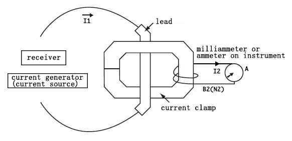
The current clamp works the same way(As shown in Figure 2), the B2 coil is mounted on a magnetic material "core" that is hinged together and then clamped onto the conductor of current I1.At this time, the measured wire clamped is equivalent to the primary coil B1 of the current transformer, and the coil B2 clamped on the conductor will get the induced secondary current:
I2(Current clamp output)=N1/N2*I1,I2=I1/N2(Where N1=1, the formula can also be written: I2=I1/N2(current clamp coil turns).Because the measuring current is too large to be borne by the meter, and it is impossible to break the measuring loop, it is usually difficult to obtain the measurement results of I1 directly and easily.To provide an effective output, a number of coils are wound around the current clamp itself. Figure 2
If N2 is 1000 turns, then the ratio is 1000:1, or expressed as 1mA/A(each 1mA current represents 1A measurement current). In addition, there are 500:5,1000:5, 2000:5, 3000:5, 2000:1, 2500:1, 3000:1 and other options.
Current clamp and multi-meter are often used together, 1000:1 current clamp (model: S50 or P50) output 1mA/A measurement value, the current passing through the current clamp will be output in a certain proportion.
The current clamp connects to the digital multi-meter and sets the AC range control output. At this time, the measured current size is the universal representation number multiplied by the variable ratio. (For example, a reading of 150mA on a multi-meter indicates that 150mA*1000=150A is flowing over the measured conductor).
In addition, the current clamp can also be used in conjunction with equipment with input impedance requirements to measure current. (As shown in Figure 3). Figure 3
The current clamp can also output AC/DC voltage to meet the current measurement requirements of instruments that only respond to the voltage range (such as recorders, oscilloscopes, energy meter field calibrators, power quality analyzers, phase meters ground resistance testers, etc.). (As shown in Figure 4 and Figure 5) Figure 4
 Figure 5
The voltage can be obtained by adjusting the output in the current clamp (For example: P18, P50, S50 & S120, etc.), and the output voltage is proportional to the measured current. Figure 6 Current clamp
Welcome electrical engineers to the company's website www.gfuve.com to carry out technical exchange!